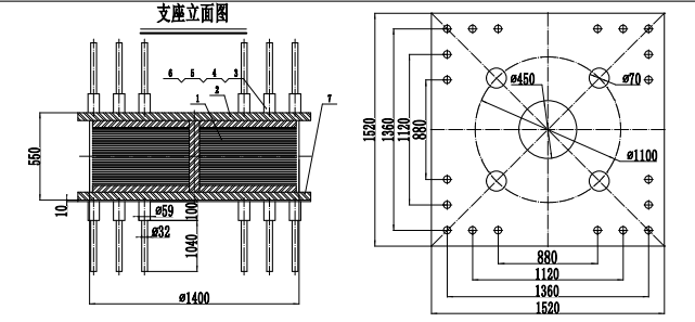
1. Requirements for Supporting Piers in the Isolation Layer
The dimensions of the supporting piers in the isolation layer shall generally be larger than the plan dimensions of the installed seismic isolation bearings, typically extending 50-100mm beyond each side of the bearing, to accommodate the position of anchor bars within the bearing embedded plate and the required concrete cover thickness.
2. Bearing Capacity Design of Supporting Piers in the Isolation Layer
The supporting piers in the isolation layer directly support the structure above the isolation level and are critical components of the seismic isolation structure. According to the requirements of the "Code for Seismic Design of Buildings", the performance level of the piers under rare earthquake actions must be essentially undamaged post-isolation. This means the piers should be designed elastically for rare earthquake conditions.
The bearing capacity of the piers shall be verified using the vertical force, horizontal force, and moment at the bottom of the seismic isolation bearings under rare earthquake actions for the isolated structure. Load effect combinations shall consider partial factors but shall not consider adjustment factors related to the seismic grade.
Design of the Isolation Layer
To ensure the seismic isolation structure achieves its isolation effect under rare earthquakes, the isolation layer must meet necessary detailing requirements.
Structural Requirements for Beams and Slabs in the Isolation Layer
To ensure the isolation layer works integrally and coordinately, a beam and slab system with sufficient in-plane stiffness shall be provided at the top of the isolation layer. When using cast-in-situ composite reinforced concrete floor slabs, the grid beam system above the bearings should be cast-in-place to enable the transfer of vertical loads and coordinate the distribution of horizontal shear forces among the seismic isolation bearings. To increase the in-plane stiffness of the top beams and slabs in the isolation layer, their cross-sectional dimensions and reinforcement should be increased.
A beam-slab type floor system shall be provided at the top of the isolation layer, meeting the following requirements:
(1) Areas related to the seismic isolation bearings shall utilize cast-in-place or cast-in-situ composite concrete beam-slab structures. The thickness of the cast-in-place slab shall not be less than 160mm. When using precast composite reinforced concrete slabs, the thickness of the cast-in-place topping should not be less than 50mm, reinforced with two-way steel mesh. The diameter of the reinforcement should not be less than 6mm, and the spacing should not exceed 250mm.
(2) The stiffness and bearing capacity of the beams and slabs at the top of the isolation layer should be greater than those of typical floor beams and slabs. The primary and secondary beams directly above the seismic isolation bearings shall be of cast-in-place reinforced concrete construction.
(3) Beams, columns, piers, etc., connected to the seismic isolation bearings shall be designed for horizontal shear and vertical local bearing capacity. Reliable detailing measures shall be taken, such as closer stirrup spacing or the provision of mesh reinforcement.
(4) When the superstructure above the isolation layer is a masonry structure, the construction of the grid beams in the first-floor slab must comply with the detailing requirements for reinforced concrete supporting beams under masonry walls in bottom-frame masonry buildings specified in GB50011 "Code for Seismic Design of Buildings". Specifically:

a. The beam width shall not be less than 300mm, and the beam depth shall not be less than 1/10 of the span.
b. The stirrup diameter shall not be less than 8mm, and the spacing shall not exceed 200mm. Within the beam ends over a length of 1.5 times the beam depth (but not less than 1/5 of the clear span), and within a length of 500mm on each side of openings in the upper wall (but not less than the beam depth), the stirrup spacing shall not exceed 100mm.
c. Side-face reinforcement shall be provided along the beam depth, with a minimum of 2Φ14 bars, and the spacing shall not exceed 200mm.
d. The longitudinal reinforcement and side-face reinforcement of the beam shall be anchored in the columns according to the requirements for tensile reinforcement. The anchorage length of the longitudinal reinforcement in the column above the support shall meet the relevant requirements for reinforced concrete transfer beams.
Connection Details for Seismic Isolation Bearings and Damping Devices
The connection details for seismic isolation bearings and damping devices shall meet the following requirements:
(1) Seismic isolation bearings and damping devices shall be installed in locations accessible for maintenance personnel.
(2) The connectors between the seismic isolation bearings and the superstructure/substructure shall be capable of transmitting the maximum horizontal shear and moment experienced by the bearings under rare earthquake conditions. Reliable connections must be provided between the seismic isolation bearings and the superstructure/substructure.
(3) Exposed embedded parts shall have reliable corrosion protection measures. The anchor bars of embedded parts shall be securely connected to the steel plate. The anchorage length of the anchor bars should be greater than 20 times the bar diameter and shall not be less than 250mm.