Home < News < Common Damage and Abnormal Conditions of Laminated Elastomeric Bridge Bearings: A Systematic Guide from Cause Diagnosis to Graded Treatment
Laminated elastomeric bearings are the most commonly used load-transfer components in small- and medium-span highway bridges. Although simple in construction—alternating rubber layers and steel plates, vulcanized into a single unit—they endure complex actions far beyond design expectations: vertical loads, horizontal shear, girder end rotation, thermal cycling, chemical attack, and dynamic fatigue.
As a result, bridge bearing damage rarely occurs suddenly. It accumulates slowly and becomes visible only when a critical threshold is reached. Based on current standards and recent field inspection data, this article systematically reviews common damage and abnormal conditions of laminated elastomeric bearings from three perspectives: cause mechanism, diagnosis technology, and graded treatment. It aims to provide field engineers with an actionable framework.
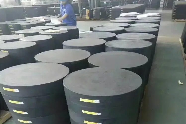
Initial shear deformation in the longitudinal or transverse direction, appearing shortly after installation, is one of the most easily overlooked abnormalities.
Its causes are not complex: temperature changes and concrete shrinkage/creep, or artificial movement of the girder during lowering. The problem is that many site personnel mistake it for “normal elastic deformation” and ignore it.
This needs correction. The allowable tangent of shear angle for laminated elastomeric bearings is ≤0.7 when braking force is included, and ≤0.5 when not. Sustained shear beyond these limits keeps rubber layers under high strain, accelerates molecular chain scission and aging, and shortens service life.
A practical response is: do not remove temporary supports immediately after girder lowering. Inspect each bearing for initial shear. If found, slightly lift one end of the girder, and the bearing will self-reset under its own elasticity. Re-inspect before bridge deck paving, when shrinkage and creep have stabilized and each girder end can be lifted individually. Missing this window greatly increases later repair costs.
Under vertical load, laminated elastomeric bearings often show wave-like surface unevenness on the sides. Theoretically, this is a normal mechanical response of the layered structure: rubber layers bulge outward, steel plates indent relatively.
The key to judging abnormality is whether the waviness is essentially uniform around the perimeter. If the wave pattern differs significantly on the same bearing, two problems are likely.
First, eccentric loading—the load point deviates from the geometric center. In mild cases, waviness becomes uneven; in severe cases, one side voids. Finite element analysis shows that when the void ratio exceeds 20%, the maximum stress in the internal steel plates exceeds code limits, and performance degradation accelerates.
Second, uneven embedded steel plates at the girder bottom, often caused by welding anchor bars without leveling, creating curved deformation. After girder placement, this forces premature edge loading on the bearing.
The former requires checking the flatness and parallelism of the girder bottom and bearing plinth before lifting, and eliminating wedge shimming after girder placement. The latter should be solved during fabrication of the embedded steel plate. For already prefabricated girders that cannot be adjusted, epoxy resin can be used to level the embedded steel plate—a cost-effective remedy.
A PTFE sliding laminated elastomeric bearing requires a friction coefficient ≤0.03. This means sliding should occur when horizontal shear exceeds 3% of the vertical load.
In practice, however, PTFE sliding bearings often fail to slide, resulting in large shear deformation. The root cause is almost always construction: contaminants on the sliding surface, rough stainless steel plate, or missing silicone grease.
Correct procedure: clean the PTFE plate and stainless steel surface with acetone or alcohol and lint-free cloth; fill the grease reservoir with specified silicone grease; verify the sliding surface before girder lowering.
For installed bearings showing excessive shear deformation, back-calculate the friction coefficient using site conditions; use 0.05–0.06 to cover adverse conditions. The gap between this value and the theoretical 0.03 reflects actual construction quality control.
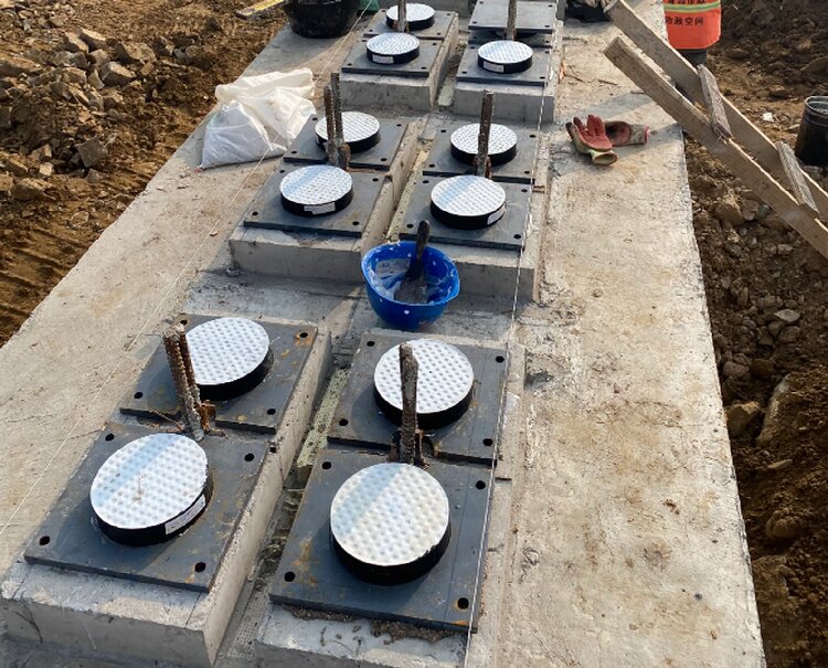
Traditional bearing inspection relies heavily on visual observation. It can detect cracking, voiding, and obvious displacement, but not internal aging, steel plate corrosion, or rubber-steel bond quality.
Non-destructive testing (NDT) is changing this. Infrared thermography is one of the most practical methods. It uses the relationship between bearing defects and temperature fields: voiding causes stress concentration and local temperature rise; internal defects create different heat conduction characteristics. With a wide temperature range of -20°C to 80°C and isotherm tracking, it can identify temperature anomalies at 0.1°C level, suitable for rapid screening of bearing groups on operating bridges.
Ultrasonic testing uses reflection and scattering of stress waves at interfaces to identify internal voids, delamination, and debonding. Combining these with visual inspection creates a progressive diagnostic chain from surface to interior.
However, upgraded detection does not automatically produce treatment decisions. The key is converting inspection results into quantitative judgments of remaining bearing performance, considering service life, environmental exposure, and load history.
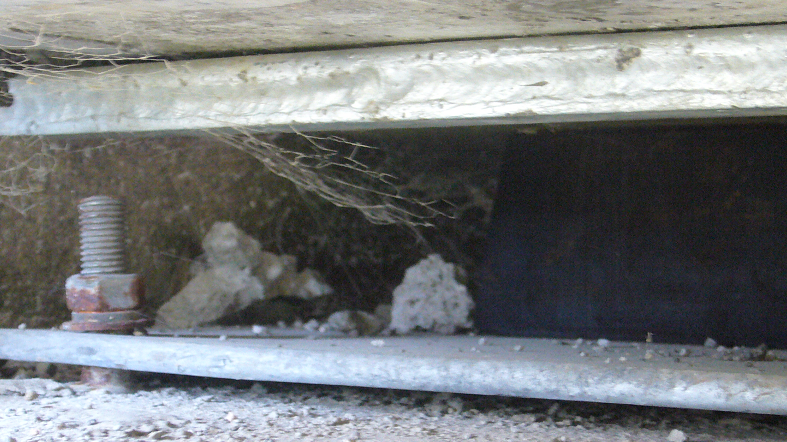
A common mistake is to replace all abnormal bearings. This is costly and disruptive, especially on busy routes. A more rational approach is graded treatment.
For early surface damage—minor cracking, uneven waviness without voiding—monitor and record, with periodic re-inspection using infrared thermography or ultrasonic testing to track progression.
For moderate damage—void ratio 10–20%, shear angle approaching but not exceeding limits, local steel plate corrosion—intervene by jacking adjustment, epoxy repair, or re-treatment of sliding surfaces to delay structural deterioration.
Only when void ratio exceeds 20%, shear angle persistently exceeds limits, or rubber-steel debonding or bursting occurs should bearing replacement become necessary.
The core premise: treatability depends on timing of discovery, not on the severity label of the damage. Early identification is far more valuable than late replacement decisions.
Damage and abnormal conditions of laminated elastomeric bearings are rarely caused by a single factor. Temperature, load, material aging, construction deviation, and environmental attack couple continuously over the service life, jointly determining actual bearing life.
Effective bearing damage management should not be a passive response of “abnormality—cause—repair.” It should extend forward to installation quality control and backward to periodic NDT inspection, forming a full life-cycle process management system.
The current JT/T 4-2019 standard for highway bridge laminated elastomeric bearings, compared with older versions, adds service life requirements and optimizes model designation. This signals a shift from “can it be used” to “how long can it be used.” In this transition, field engineers’ ability to identify abnormal bearing conditions and make treatment decisions will directly affect the safety and economy of the bridge life cycle.
Initial shear deformation is the longitudinal or transverse shear that appears shortly after bearing installation, caused by temperature changes, concrete shrinkage and creep, or girder movement during lowering. It should be corrected before deck paving.
Bridge bearing inspection combines visual inspection, infrared thermography, and ultrasonic testing. Visual inspection identifies surface cracks, voiding, and displacement. Infrared thermography detects temperature anomalies from internal defects. Ultrasonic testing identifies internal voids, delamination, and debonding.
Bearing replacement is recommended when void ratio exceeds 20%, shear angle persistently exceeds code limits, or rubber-steel debonding or bursting occurs. Early-stage damage should be monitored or repaired rather than replaced immediately.
The allowable tangent of shear angle is ≤0.7 when braking force is included, and ≤0.5 when not. Sustained shear beyond these limits accelerates rubber aging and reduces service life.
A PTFE sliding bearing may fail to slide due to contaminants on the sliding surface, rough stainless steel plate, or insufficient silicone grease. Proper cleaning and greasing before installation are essential to achieve the specified friction coefficient ≤0.03.