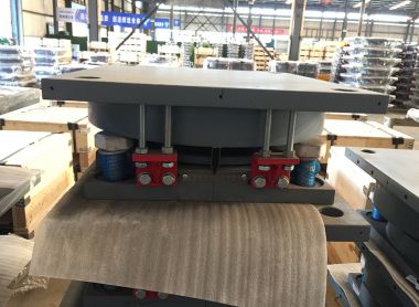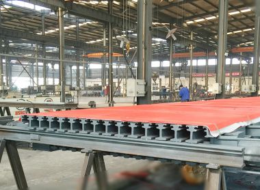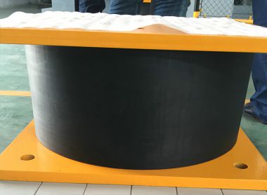
Elastomeric bearings are widely used in medium- and short-span bridges. They can be manufactured as plain elastomeric bearing pads (composed solely of elastomer) or as steel-reinforced (laminated) elastomeric bearings, which consist of alternating layers of steel reinforcement and vulcanized elastomer bonded together.
These bearings are designed to transfer vertical loads while accommodating relative displacements between the bridge superstructure and its supports. For smaller bridges with limited vertical loads, translations, and rotations, plain elastomeric pads are often sufficient. For larger bridges – especially those subjected to significant vertical forces, movements, and rotations – laminated (steel-reinforced) elastomeric pads are preferred. Field performance data confirm that elastomeric bearings perform reliably when designed within the material’s structural limits. Detailed design and construction requirements are provided in LRFD [14] and the AASHTO LRFD Bridge Construction Specifications, 2nd Edition (2004), Section 18.
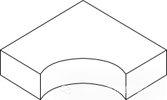
Proper control of deflection under both total load and live load is critical for the service performance of deck joints, seals, and other bridge components. The relative deflection across expansion joints must be evaluated carefully.
LRFD [C14.7.5.3.6] recommends that the maximum relative live-load deflection at joints be limited to 1/8 inch. Laminated (steel-reinforced) elastomeric bearings exhibit a nonlinear load-deflection curve under compression. In the absence of specific elastomer data, LRFD Figure 14.7.6.3.3-1 may be used as a reference. Creep effects should be determined using the specific elastomer compound’s material properties.
The instantaneous compression deflection, δ, can be calculated using the method specified in LRFD [14.7.5.3.6, 14.7.6.3.3] or the following formula:
δ = Σ εᵢ · hᵣᵢ
Where:
δ = instantaneous deflection (in.)
εᵢ = instantaneous compressive strain in the i th elastomer layer of a fiber-reinforced composite bearing
hᵣᵢ = thickness of the i th elastomer layer (in.)
According to LRFD [14.7.6.3.3], under service limit state (without dynamic load allowance), the initial compression deflection in any layer of a plain or laminated bearing must not exceed 0.07·hᵣᵢ.
If the service dead-load stress is less than 200 psi, the bearing pad must be secured against horizontal movement.
The horizontal force component caused by deformation of the elastomer is calculated per LRFD [14.6.3.1] using:
Hᵤ = (G · A · Δᵤ) / hᵣₜ
Where:
Hᵤ = horizontal force from applicable strength load combinations (kip)
G = shear modulus of the elastomer (ksi)
A = plan area of the bearing (in.²)
Δᵤ = factored shear deformation (in.)
hᵣₜ = total elastomer thickness (in.)
The steel reinforcement plates must be verified in accordance with LRFD [Formulas 14.7.5.3.5-1, 2]:
hₛ ≥ (3 · hₘₐₓ · σₛ) / Fᵧ
hₛ ≥ (3 · hₘₐₓ · σₗ) / ΔFₜₕ
Where:
hₛ = steel plate thickness (in.)
hₘₐₓ = thickness of the thickest elastomer layer (in.)
σₛ = average service compressive stress due to total load (ksi)
Fᵧ = yield strength of steel (ksi)
σₗ = average service compressive stress due to live load (ksi)
ΔFₜₕ = constant amplitude fatigue threshold for Category A (ksi), per LRFD [6.6]
If holes are present in the steel plate, the minimum thickness shall be increased by a factor equal to twice the total width divided by the net width.
Rotation control ensures that no point in the bearing experiences net uplift between the bearing and the structure, and that shear strains in the elastomer are kept within acceptable limits. Rotation checks shall be performed using the criteria in LRFD [14.7.6.3.5] and the equations below:
For laminated (steel-reinforced) elastomeric pads [LRFD 14.7.6.3.5d-1,2]: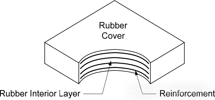
Where:
σₛ = average service compressive stress due to total load at maximum rotation (ksi)
G = elastomer shear modulus (ksi)
S = shape factor of the thickest elastomer layer
L = length of rectangular bearing (parallel to bridge axis) (in.)
hᵣₜ = total elastomer thickness (in.)
hᵣᵢ = thickness of the i th elastomer layer in a laminated bearing (in.)
W = width of bearing transverse to bridge axis (in.)
θₛ,ₓ = service rotation due to total load about the transverse axis (rad.)
θₛ,₂ = service rotation due to total load about the longitudinal axis (rad.) – (not considered in certain cases)
n = number of internal elastomer layers. An “internal layer” is defined as a layer bonded to surfaces on both sides; an exterior layer is bonded on only one side. When the thickness of an exterior layer exceeds half the total elastomer thickness, the parameter n may be increased by half a layer per additional exterior layer.
Over many years, plain elastomeric bearing pads have performed excellently in prestressed concrete girder bridges. For standard details, refer to the Prestressed Concrete Beam Bearing Pad Details. In typical applications, these bearings are cast into the concrete beam haunch, with a ½ inch plain elastomeric pad placed on the beam. For laminated (steel-reinforced) bearings, detailed dimensioning of steel plates and elastomer layers is provided in the Standard for Elastomeric Bearings for Prestressed Concrete Beams.
For further information, always consult the latest AASHTO LRFD Bridge Design Specifications and relevant material data sheets to ensure compliance and optimal performance of your bridge bearing design.