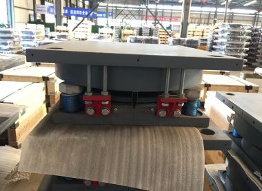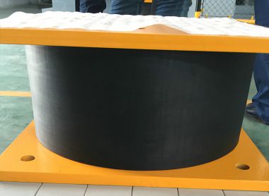
Lead Rubber Bearings (LRB) are passive seismic isolation devices widely used in bridges and buildings to mitigate earthquake-induced vibrations-. Comprising multiple layers of rubber laminated to steel plates with a central lead core, LRBs provide both vertical load capacity and horizontal flexibility, while the lead core dissipates seismic energy through hysteretic deformation-. The design of an LRB is a multi-objective optimization problem that requires careful balancing of stiffness, damping, and displacement capacity. Drawing from a practical design example for a bridge project, this article discusses the key parameters that govern LRB performance and the critical trade-offs engineers must navigate.
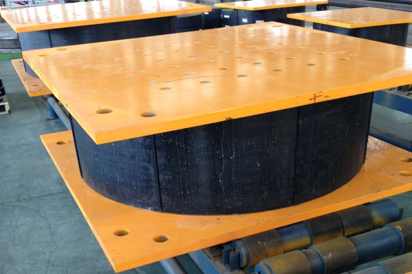
Not all LRB parameters carry equal weight. Sensitivity analyses have demonstrated that among geometric and material variables, the lead core radius is the most dominant parameter affecting LRB performance, whereas the number of rubber layers has the least contribution-8-. This finding underscores a fundamental truth in LRB design: the lead core is the primary engine of energy dissipation, and its sizing deserves primary attention.
The lead core diameter directly governs the bearing’s characteristic strength (Qd)—the force level at which the lead yields and begins dissipating energy through hysteresis-. In the design example presented, the characteristic strength was initially calculated as 5.09 tons (5% of the axial load) and later refined to 6.49 tons-, reflecting the iterative nature of LRB parameter tuning.
The characteristic strength, normalized by the weight acting on the isolator (Qd/W), is one of the most influential parameters for seismic response-24. A larger Qd increases energy dissipation but also raises the force transmitted to the structure. Research indicates that for a given ground motion, there exists an optimal Qd/W value that minimizes both maximum isolator displacement and maximum isolator force simultaneously-24. This optimization is particularly critical for near-fault ground motions, which may require damping ratios approaching 50% to control displacements effectively-.
The effective stiffness (Keff) and equivalent damping ratio (Beff) are the two primary performance parameters that characterize LRB behavior-1. In the design example, the effective stiffness was computed as 142.56 Tn/m with an effective damping of 14.01%-—values that reflect the specific seismic demand of the project site.
These parameters are not fixed material properties; they are significantly influenced by horizontal loading frequency and vertical load-1-. This load-dependency means that laboratory characterization tests must replicate actual service conditions to yield meaningful design values. Furthermore, the effective stiffness and damping ratio are interdependent: increasing the lead core diameter raises both the energy dissipated per cycle and the effective stiffness, requiring careful calibration.
LRBs are typically modeled as bilinear elements characterized by an elastic stiffness (Ke), a yield force (Fy), and a post-yield stiffness (Kd)-. The ratio of post-yield to elastic stiffness (Kd/Ke)—often referred to as the hardening ratio—directly influences the bearing’s force-displacement response-24.
In the design example, this ratio was calculated as 0.10-, indicating that after yielding, the bearing retains only 10% of its initial stiffness. This low post-yield stiffness is desirable for seismic isolation as it allows large displacements with limited force increase, but it must be balanced against the need for stability and self-centering.
While LRBs are primarily designed for horizontal seismic isolation, vertical stiffness is equally critical for supporting gravity loads and maintaining structural stability. The vertical stiffness is governed by the rubber compound’s compression modulus, the bearing’s plan area, and the shape factor (S)—the ratio of the loaded area to the area free to bulge-. In the example, a vertical stiffness of 51,753 Tn/m was achieved-.
The shape factor is a particularly important parameter: it must be sufficiently high to prevent excessive vertical deformation under service loads while remaining low enough to permit the horizontal flexibility required for seismic isolation-. The design example adopted a shape factor of 9.82-, consistent with typical practice for bridge applications.
The total rubber height (Hi) determines the bearing’s ultimate shear deformation capacity. In the example, a rubber height of 176 mm was selected to accommodate a maximum total displacement (DTM) of 360 mm-, yielding a shear strain of approximately 200%—a typical design limit for elastomeric bearings-.
This parameter represents a critical trade-off: increasing rubber height enhances displacement capacity but also increases bearing size, cost, and the potential for instability under large deformations-. The design must therefore balance seismic demand against practical constraints of manufacturability and constructability.
The design example illustrates the iterative nature of LRB design. The process begins with seismic demand characterization—spectral acceleration, assumed period, and effective damping—to establish the target displacement-. The bearing diameter is then sized based on axial load and allowable compressive stress-. Only after these foundational parameters are established does the designer proceed to lead core sizing, rubber height determination, and stiffness calculations-.
This sequential approach reflects a fundamental reality: LRB design is a system-level problem. No single parameter can be optimized in isolation. The lead core diameter, rubber height, bearing diameter, and material properties must be co-evolved to achieve a solution that satisfies all performance criteria—displacement, force, damping, stability, and vertical load capacity—simultaneously.
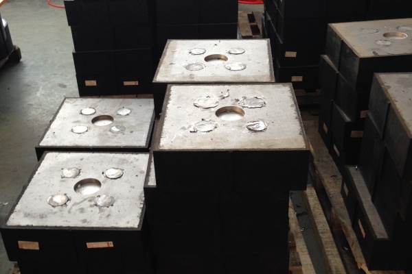
The design of Lead Rubber Bearings hinges on a handful of critical parameters, with the lead core radius emerging as the single most influential variable-8. However, effective design requires holistic consideration of characteristic strength (Qd), effective stiffness (Keff), damping ratio (Beff), vertical stiffness (Kv), and rubber height—each of which must be tuned to the specific seismic hazard, structural system, and performance objectives of the project-11.
The design example reviewed here demonstrates that successful LRB design is not about identifying a single “most important” parameter, but rather about navigating the complex trade-offs between energy dissipation, stiffness, and displacement capacity. As seismic design codes continue to evolve and our understanding of LRB behavior deepens—particularly regarding rate-dependency, vertical load effects, and tension stiffness-4—the importance of rigorous, parameter-sensitive design methodologies will only grow.