Keywords: elastomeric bearing pad, laminated rubber bearing, bridge bearing design, AASHTO LRFD, shear deformation, compression stress, rotation check, steel reinforcement
Introduction: Why Bearing Design Matters
Bridge bearings are small but critical components that connect the superstructure to the substructure. Among them, laminated elastomeric bearings (steel reinforced rubber pads) are widely used in medium and short span bridges due to their simplicity, cost effectiveness, and excellent deformation capacity. However, many engineers rely on empirical sizing without performing the full set of checks required by modern codes – leading to premature extrusion, slippage, or delamination.
This article provides a systematic design procedure based on internationally accepted practice (primarily AASHTO LRFD). We will walk through the entire process – from selecting the bearing type to verifying shear, compression, stability, deflection, steel plate thickness, and rotation – so you can confidently design a safe and durable bearing.
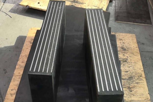
There are two basic categories:
Plain elastomeric pad – solid rubber without internal reinforcement. Low load capacity, suitable only for small loads and movements.
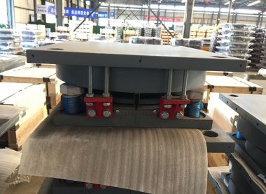
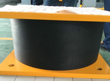
Laminated (steel reinforced) elastomeric bearing – thin steel plates bonded between rubber layers. This greatly increases vertical stiffness and compressive strength while retaining high shear flexibility – the most common choice for modern bridges.
·
Important: The code prohibits tapered elastomeric layers in reinforced bearings. Also, the bearing must be installed on a level surface. If the beam soffit has a slope or rotation, a tapered steel plate (minimum thickness 1½ inches) must be used to create a horizontal bearing surface; otherwise, gravity will induce additional shear strain.
AASHTO LRFD offers two design approaches:
Method A (based on NCHRP 248) – simpler calculations, no special testing required, but more conservative stress limits.
Method B (based on NCHRP 298) – allows higher stresses but requires specific elastomer testing and stricter quality control.
For typical medium span bridges, Method A is adequate. If you need to reduce bearing size or increase load capacity, Method B can be considered, but weigh the additional testing costs.
Begin by selecting the total thickness (H), length (L) (along bridge axis), and width (W) (transverse).
H can be initially estimated from the bridge expansion length, using standard design tables (e.g., for prestressed concrete girders).
L must satisfy stability requirements (discussed later).
W is usually taken as the bottom flange width of the beam, minus a clearance (e.g., 2 in for prestressed beams, 6 in for wide flange sections, or full web width for steel girders).
These initial values will be adjusted after the subsequent verifications.
The bearing undergoes horizontal shear due to temperature changes, shrinkage, and creep. The total shear deformation ΔsΔs must satisfy:
hrt≥2Δshrt≥2Δs
where hrthrt is the total rubber thickness. For prestressed concrete girders, additional creep and shrinkage deformation (estimated as expansion length × 0.0003 ft/ft) must be added to the thermal movement.
At the service limit state, the average compressive stress σsσs must not exceed:
Plain pad: σs≤0.80σs≤0.80 ksi
Laminated bearing: σs≤1.25σs≤1.25 ksi and σs≤1.25GSσs≤1.25GS
where GG is the shear modulus of the elastomer, and SS is the shape factor – a key parameter defined as the loaded area divided by the area free to bulge. For a rectangular bearing:
S=L⋅W2⋅hri⋅(L+W)S=2⋅hri⋅(L+W)L⋅W
where hrihri is the thickness of a single internal rubber layer. All internal layers must have the same thickness, and the cover layers cannot exceed 70% of the internal layer thickness.
The total bearing thickness HH must not be too large relative to its plan dimensions, otherwise buckling may occur. The code requires:
H≤L3andH≤W3H≤3LandH≤3W
In other words, thickness must be ≤ one third of both length and width.
Excessive vertical deflection can cause relative movements at deck joints, affecting ride quality and joint seals. The instantaneous compression deflection δδ is calculated by summing the strain of each rubber layer. Moreover, for any single layer, the initial compression strain must not exceed 0.07hri0.07hri. If the service dead load stress is less than 200 psi, the pad must be anchored to prevent horizontal movement.
Internal steel plates must satisfy both strength and fatigue requirements. The plate thickness hshs must be checked against:
Strength condition (based on yield strength FyFy)
Fatigue condition (using the constant amplitude fatigue threshold ΔFTHΔFTH, typically 24 ksi for Category A)
If holes are present in the plates, the required thickness must be increased proportionally (by the ratio of gross width to net width).
Due to beam rotation, the bearing may experience uneven compression, potentially causing partial uplift. The rotation check ensures that no net tension occurs at any point and that the rubber shear strain is within limits. For laminated bearings, the verification involves σsσs, GG, SS, LL, WW, hrthrt, and the rotation angles θsθs about both axes. Both longitudinal and transverse rotations must be evaluated.
For preliminary design, the following values (commonly used by Wisconsin DOT) are a good starting point:
Parameter | Value |
Cover layer thickness | ¼ in |
Internal layer thickness | ½ in |
Elastomer hardness | Shore A 60 ±5 |
Shear modulus GG | 0.1125 ~ 0.165 ksi |
Creep ratio (25 year / instantaneous) | 0.30 |
Steel plate thickness | ⅛ in |
Steel yield strength | 36 ksi or 50 ksi |
Fatigue threshold (Category A) | 24 ksi |
Collect input data – dead load, live load + dynamic allowance, minimum vertical load, design rotations, translations, expansion length, temperature zone, and beam web/flange dimensions.
Choose bearing type – plain or laminated.
Select preliminary properties – dimensions and materials.
Check shear deformation (LRFD 14.7.6.3.4).
Check compression stress (LRFD 14.7.6.3.2).
Check stability (LRFD 14.7.6.3.6).
Check compression deflection (LRFD 14.7.5.3.6 / 14.7.6.3.3).
Design anchorage (if required).
Verify steel plate thickness – strength and fatigue (LRFD 14.7.5.3.5 / 14.7.6.3.7).
Check rotation (LRFD 14.7.6.3.5).
If any verification fails, adjust the dimensions or material properties and iterate until all criteria are satisfied.
Conclusion: A Well Designed Bearing Is Calculated, Not Guessed
Designing a laminated elastomeric bearing is not merely picking a standard size from a catalog. It requires a systematic evaluation of loads, displacements, rotations, and material behavior. This article has presented a clear step by step methodology based on AASHTO LRFD, helping you understand the rationale behind each check. For real projects, we recommend using a dedicated spreadsheet or finite element analysis to balance safety and economy.
If you are interested in detailed calculation examples or derivation of the formulas, feel free to leave a comment below – we will cover them in future posts.